
LED Emergency Driver Buyer Guide
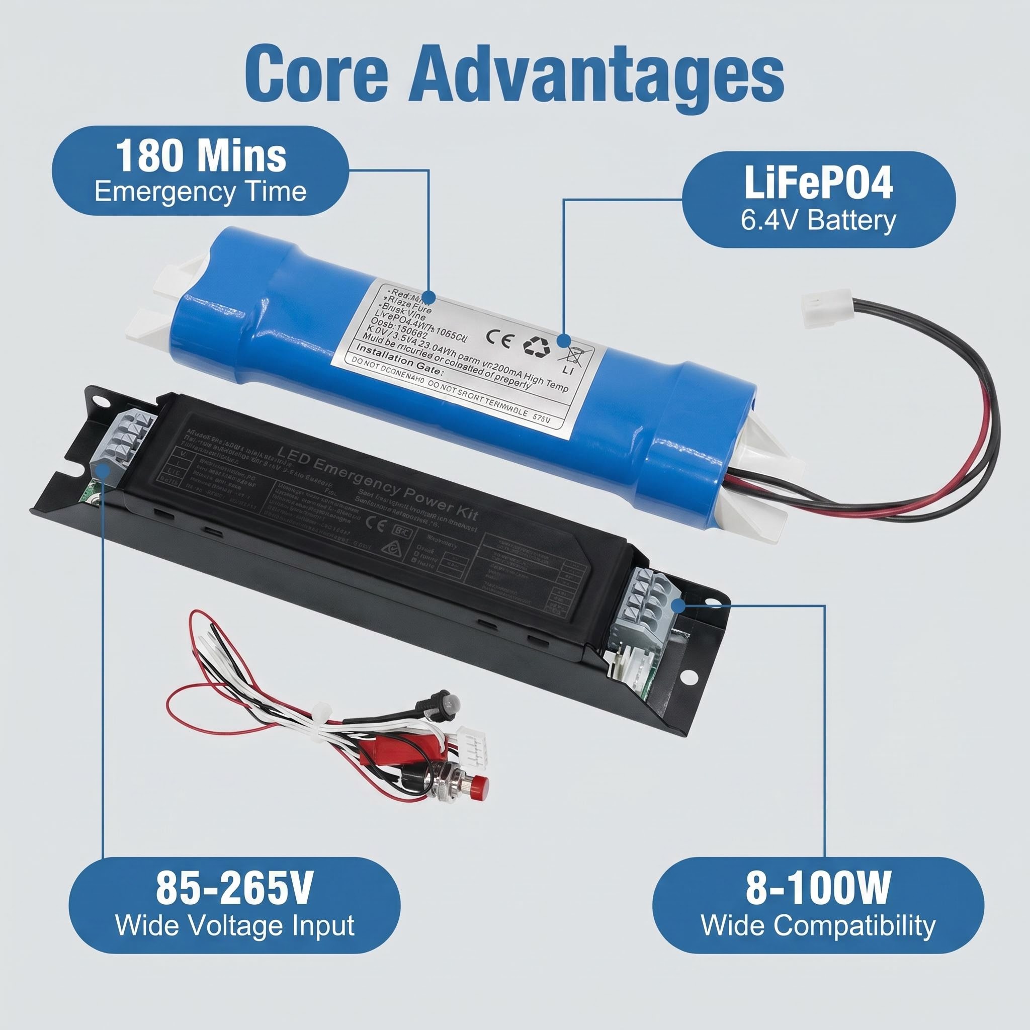
An LED emergency driver is a self-contained control gear unit that monitors mains power, charges a standby battery, and—on power failure—inverts that stored DC energy into a constant current output to keep an LED luminaire alive for the emergency duration the local code demands. Its seven functional blocks are the enclosure, charging circuit, battery pack, constant current inverter, changeover circuit, status indicator and test facility, and wiring harness with connectors; each block has a cheap-spec version that will degrade or fail inside the design life of the host fixture.
The rest of this page walks those sub-assemblies in order, shows what a cut-corner implementation looks like versus a build that meets EN 60598-2-22 or UL 924 stress tests, and flags the failure mode that typically kills each part first. Use this to read past glossy datasheets and ask suppliers the questions that reveal whether the driver will last five years in a 45°C ceiling plenum or need replacement at the first annual test.
Enclosure and Thermal Path
The enclosure does three jobs: houses live parts safely, dissipates heat from the inverter MOSFETs and charge controller, and provides the IP rating that keeps dust and moisture off the battery terminals. A cheap driver uses a folded steel box with no internal ribbing, painted rather than plated terminals, and an IP20 rating only; in a humid Middle Eastern warehouse or Southeast Asian car park, condensation at the battery terminals causes creeping corrosion and high-resistance joints within 18 months. A specification-grade housing is die-cast aluminium or flame-retardant ABS+PC with internal mounting bosses that keep the LiFePO4 cell block thermally coupled to the shell, rated IP65 for dust-tight and jet-proof operation, and carries an ambient range of -20°C to +50°C or wider. The failure that appears first in cheap enclosures is terminal corrosion leading to charge voltage drop; the battery never reaches full charge, and the first duration test fails at 45 minutes instead of the required 90 minutes.
Charging Circuit
The charging circuit is a switched-mode or linear regulator that converts AC mains to a controlled DC float voltage matched to the battery chemistry: 3.65V per cell for LiFePO4, 4.2V for Li-ion 18650, or 1.45V per cell for NiCd. A cheap charger uses a fixed resistor and diode network with no temperature compensation; at +40°C ambient the float voltage drifts high enough to gas a NiCd cell or degrade a lithium cell’s SEI layer, cutting cycle life from 500 cycles to under 200. A proper charger has a two-stage profile—constant current to 80% state of charge, then constant voltage with dT/dt termination for NiCd or current taper for LiFePO4—and recalibrates every 28 days in self-test mode per EN 62034. Charge time to 80% capacity is typically 24 hours for a 3.2V 3000mAh LiFePO4 pack, 48 hours for larger 7.4V 2600mAh Li-ion configurations. The first failure mode in cheap chargers is capacitor drying in the SMPS primary; the output ripple increases, the battery receives pulsed overvoltage, and capacity fades 30% in the first year.
Pacchetto batterie
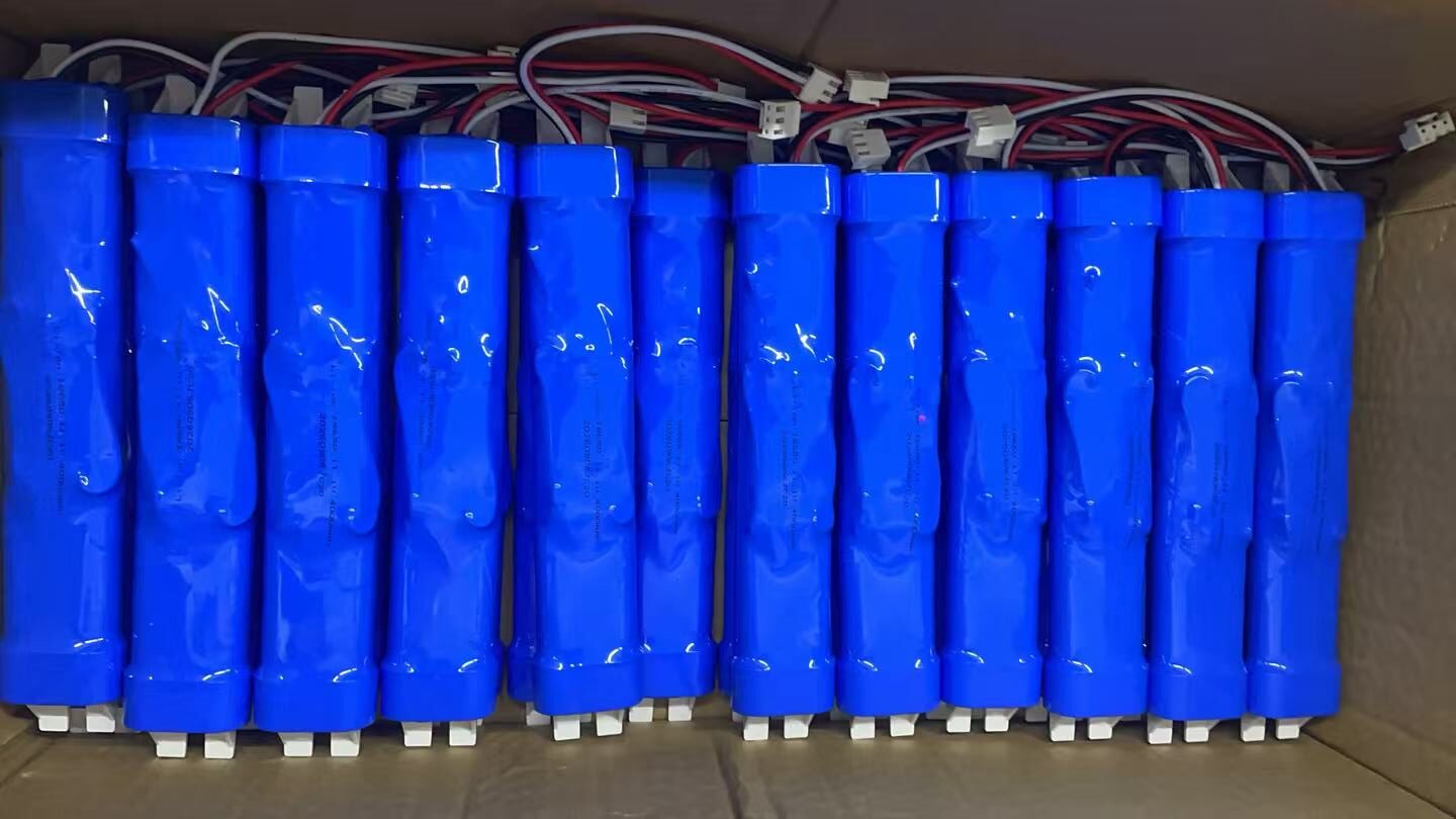
The battery pack stores the energy that determines emergency duration. For a 10W LED panel emergency load at 120lm/W, 90 minutes requires roughly 18Wh usable; a 3.2V LiFePO4 pack at 3000mAh (9.6Wh) needs three cells in series for 9.6V, or parallel strings to hit the watt-hour target. A cheap supplier ships NiCd 3.6V 600mAh packs that weigh less and cost less but deliver only 2.2Wh; the same 10W load dies in 13 minutes. Li-ion 18650 3.7V 2600mAh cells offer higher energy density but demand a protection PCB with cell balancing and temperature cutoff; without it, a single weak cell in series drags the whole string down and the inverter trips on undervoltage at minute 62. LiFePO4 tolerates 800 to 1500 cycles at 80% depth of discharge versus 300 to 500 for standard Li-ion and 200 to 300 for NiCd, but the trade-off is 30% heavier weight per watt-hour. The first failure in cheap packs is cell mismatch in unbalanced strings; one cell swells, internal resistance rises, and the pack delivers only 60% rated capacity by month eighteen.
Constant Current Inverter Output
The inverter is a DC-DC boost or buck-boost converter that takes battery voltage—anywhere from 2.5V discharged to 12.6V fully charged depending on configuration—and delivers a stable current to the LED array. EN 1838 requires emergency output to reach the declared lumen value within 5 seconds of mains failure and maintain it for the rated duration; for LED panels this is typically 10% of normal output (300lm from a 3000lm panel) for 3 hours, or 50% output (1500lm) for 1 hour if the specifier opts for a higher-lumen short-duration kit. The inverter’s output window is critical: a driver rated 50-200V DC at 150mA will not start a 24V LED strip, and a 20-40V driver will overcurrent a 54V COB module. Cheap inverters use open-loop control with no LED forward-voltage sensing; as the battery sags, output current droops and the emergency light fades below the minimum 1 lux on the escape route floor. The first failure is MOSFET avalanche breakdown from inadequate snubbing, usually at the high-temperature end of the ambient range.
Changeover Circuit
The changeover circuit switches the LED module from mains driver to emergency inverter when mains disappears, and back again on restoration. In non-maintained wiring the LED is off during normal operation and only the emergency inverter feeds it; in maintained wiring the LED runs from the mains driver and the changeover circuit transfers without flicker. The standard device is a relay with mains-voltage coil and bifurcated contacts rated for DC breaking; cheap versions use a single-pole PCB relay with silver-nickel contacts that weld shut after 200 operations at 50V DC inductive load. A solid-state changeover using back-to-back MOSFETs eliminates contact wear but adds 0.5V drop and corresponding heat; in a 10W load that is negligible, at 40W it needs a heatsink that may not fit the OEM’s fixture housing. The first failure in relay-based cheap changeovers is contact welding in the maintained position; the emergency inverter never connects, and the first power cut leaves the space dark.
Indicator and Test Facility
The indicator is a bi-colour LED or LCD showing charge status: green for healthy, red for fault, flashing for in-test. EN 62034 and BS 5266-1 require automatic testing at intervals not exceeding 28 days for functional duration and annually for full discharge; the facility may be a manual test key, a self-test microcontroller with real-time clock, or a DALI interface that reports to the building management system. A cheap driver has only the manual key; the facilities manager must walk every floor monthly, which fails in practice and means faults are found only when the emergency actually happens. Self-test adds $4 to $6 BOM cost but catches inverter faults and battery degradation before they matter; DALI adds $8 to $12 and enables central logging with addressable fault reports. The first failure in cheap indicator circuits is the surface-mount LED itself, which dims 50% in three years of continuous green operation and is no longer visible in daylight, so staff cannot tell the unit is in fault state.
Wiring and Connectors
The wiring harness brings mains live, neutral and earth to the driver, connects the LED module via a 2-pin or 3-pole connector, and routes the battery pack through a polarised plug to prevent reverse connection. Cheap drivers use 0.5mm² PVC wire rated 70°C and push-fit terminal blocks; in a 45°C ceiling void with inverter waste heat the insulation hardens, the clamp loosens, and resistance heating escalates until the terminal chars. Specification builds use 0.75mm² or 1.0mm² silicone-insulated cable rated 105°C or 150°C, screw-clamp terminals with strain relief, and battery connectors with mechanical keying. For OEMs adding emergency to their own fixtures, the connector footprint matters: a driver with 150mm flying leads and a JST SM connector drops into a panel light housing in 30 seconds; one with raw wire ends needs manual crimping and extends assembly time. The first failure in cheap wiring is terminal loosening from thermal cycling; the second is battery connector arcing from reversed insertion, which destroys the protection PCB fuse and renders the unit dead until serviced.
How a LED Emergency Driver Works
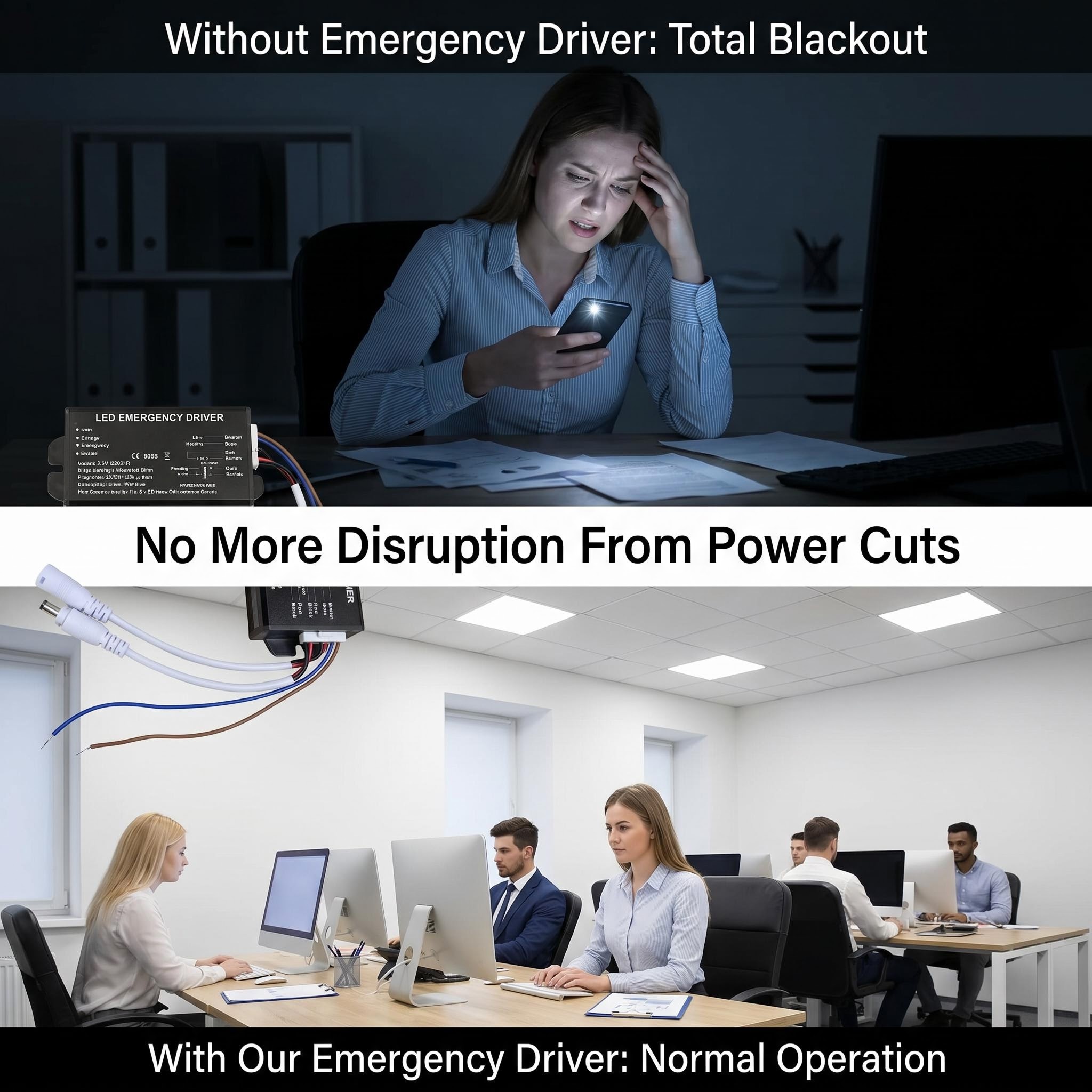
A LED emergency driver operates as a self-contained power switching and energy storage system. The sequence below is common to the parts of an emergency driver found in Hymark’s LED Emergency Driver For LED Panel Lights, LED Emergency Driver For LED Tubes, and LED Emergency Driver For Linear Lights lines.
Process Flow: Normal Standby to Emergency Operation
- Mains healthy: AC 85-265V or 220-240V feeds the charging circuit; the battery pack charges at trickle current while the changeover relay remains in normal position
- Mains failure detected: The changeover circuit senses voltage collapse below ~70% nominal within 0.5 seconds
- Changeover executes: Relay switches to battery position; the constant current inverter output activates
- Emergency discharge: Battery voltage falls from nominal (e.g., 3.2V LiFePO4 or 7.4V Li-ion 2S) through the DC-DC boost/buck stage to maintain output current
- Duration limit reached: Battery protection circuit cuts output at deep-discharge threshold, typically after 90 minutes, 2 hours, or 3 hours depending on cell capacity
- Mains restore: Changeover relay returns to normal; charging circuit resumes with recovery charge profile until full
Charging Circuit During Healthy Mains
The charging circuit performs two functions simultaneously: supplying the LED driver with uninterrupted AC pass-through, and maintaining the battery at full charge. A well-specified unit uses a two-stage charger—constant current to ~90% state of charge, then constant voltage float at 3.65V per cell for LiFePO4 or 4.2V for Li-ion 18650. Charge current is typically 0.2C to 0.5C, meaning a 3000mAh LiFePO4 pack recharges in 6 to 10 hours from full discharge.
What cheap looks like: A single resistor and diode trickle charger with no temperature compensation. NiCd packs tolerate this; LiFePO4 and Li-ion 18650 cells suffer plating, capacity fade, and thermal runaway risk. The battery reaches only 80% charge in practice, shortening the real emergency duration below the rated 90 minutes.
What fails first: The charge control IC or the electrolytic capacitor on the charge rail. Capacitors rated at 85°C in an enclosure running at 45°C ambient accumulate 5000 hours of life; at 65°C ambient, that drops below 2000 hours.
Mains Failure Detection and Changeover Speed
The changeover circuit monitors AC line voltage through a resistive divider and comparator. EN 1838 and BS 5266-1 require emergency output within 0.5 seconds of mains failure. A relay-based changeover typically achieves 10-50ms mechanical switching; solid-state switches using MOSFETs are faster but generate more heat and cost more.
What cheap looks like: A slow relay with no hysteresis, chattering at brownout voltages. The relay contacts arc, pit, and weld shut. If welded in emergency position, the unit fails silently—battery drains, charger never reconnects, and the next power cut yields darkness.
What fails first: Relay contacts after 50,000 to 100,000 operations, or sooner if the load is capacitive. Self-test cycles (EN 62034) accelerate wear; a monthly functional test plus annual duration test consumes 13 cycles per year minimum.
Battery Pack and Chemistry Trade-offs
| Chemistry | Nominal V | Typical Capacity | Cycle Life | Charge Time | Weight | Notes |
|---|---|---|---|---|---|---|
| NiCd | 3.6V (3S) | 1500-4000mAh | 500 | 12-16h | Heavy | Memory effect; cadmium restricted in EU |
| Li-ion 18650 | 3.7V (1S) or 7.4V (2S) | 2000-3500mAh | 300-500 | 4-6h | Light | Requires PCM for over-discharge protection |
| LiFePO4 | 3.2V (1S) or 6.4V (2S) | 2000-6000mAh | 1000-2000 | 3-5h | Light | Safer thermal profile; higher upfront cost |
A 3.2V 3000mAh LiFePO4 pack stores 9.6Wh. Driving a 4W emergency load at 80% inverter efficiency yields 1.9 hours actual duration. The same load on a 1500mAh NiCd pack yields under 45 minutes if the battery has aged.
What cheap looks like: Unbranded 18650 cells with no PCM (protection circuit module), or NiCd packs with mismatched cells. One weak cell in series drags the entire string into reverse polarity during discharge, destroying capacity permanently.
What fails first: Cell imbalance in multi-cell packs; electrolyte dry-out in NiCd after 3-4 years regardless of cycles.
Constant Current Inverter Output
The inverter stage converts battery DC to the current and voltage window the LED module requires. Typical output windows are DC 25-45V at 150-350mA for panels, or DC 9-18V at 200-500mA for tubes and linear fixtures. The driver must match the emergency output to the LED forward voltage curve; a mismatch means the LEDs run dim or the inverter overheats.
EN 1838 specifies minimum 10% of normal luminous flux for escape routes, or 50% for anti-panic open areas. A 4000lm panel in normal mode must deliver at least 400lm in emergency. The inverter achieves this by maintaining constant current even as battery voltage sags from 4.2V to 3.0V (Li-ion) or 3.65V to 2.5V (LiFePO4).
What cheap looks like: A simple resistor-limited output with no feedback. As battery voltage drops, current drops proportionally; light output fades below the 10% threshold in the final 30 minutes of discharge. The datasheet claims 90 minutes, but the last 20 minutes are non-compliant.
What fails first: The switching MOSFET or inductor in the boost converter. Undersized inductors saturate, causing current spikes and MOSFET avalanche failure.
Indicator and Test Facility
A bicolor LED indicator shows:
– Green: Mains healthy, battery charging
– Red: Fault (battery disconnected, charge failure, lamp fault)
– Off or flashing: Self-test in progress
Self-test functionality per EN 62034 automates the monthly functional test and annual duration test. DALI-2 emergency extensions (IEC 62386-202) report status to the building management system. A manual test key provides local override for commissioning.
What cheap looks like: A single green LED that merely indicates mains presence, not charge completion. No self-test means the fault remains hidden until a real power failure or the annual manual inspection.
What fails first: The indicator LED itself—low cost, but if it fails open, a green-absent condition is indistinguishable from a red fault without a multimeter.
Wiring and Connector Integrity
Maintained wiring brings permanent live, switched live, and neutral to the driver; the unit runs in emergency from battery regardless of wall switch position. Non-maintained wiring uses only permanent live and neutral; the wall switch kills both normal and emergency light, acceptable only where code permits (some storage areas, not escape routes).
Terminal blocks must accept 0.5-2.5mm² solid or stranded cable and retain torque after thermal cycling. Push-fit connectors save assembly time but loosen in vibrating environments.
What cheap looks like: Undersized terminals, no strain relief, or a single shared terminal for multiple functions. Loose connections arc, carbonize the block, and create high-resistance faults that the indicator may not distinguish from a lamp fault.
What fails first: The earth bond screw in plastic enclosures, or the PCB-mounted terminal block solder joint under repeated flexing.
Where Cheap Products Lose Output or Duration
At changeover: Slow relay or missing mains detection threshold calibration. The 0.5-second requirement is missed; occupants are already in darkness before emergency output begins.
At 50-70% of rated duration: Inverter current collapses as battery voltage sags. The light stays on, but below 10% output, failing EN 1838 photometric requirements. A 3-hour-rated unit with a 2000mAh battery driving 6W load is mathematically impossible (6W × 3h = 18Wh required; 7.4V × 2Ah × 0.8 efficiency = 11.8Wh available). The datasheet relies on initial lumen overage and rapid fade.
At recharge: No temperature-compensated charger. In hot plant rooms, the battery never reaches full charge; in cold warehouses, it overcharges and vents. Both conditions shorten the next emergency cycle.
LED Strip Products: Voltage Drop and Segment Layout
For Hymark’s COB LED strips and SMD LED strips used in emergency accent or egress path marking, the parts of an emergency driver interaction differs. The driver supplies DC 24V or 48V constant voltage, not constant current per LED.
A typical 24V SMD strip uses 60 LEDs per metre in 20 segments per metre, each segment 50mm with three LEDs and one current-limiting resistor in series. Cut length is 50mm. The resistor value sets segment current; at 24V input with 3.0V LED forward voltage, the resistor drops ~15V at 20mA, dissipating 300mW per segment.
Voltage drop along a run limits practical length. At 14.4W/m (60 LEDs, 24V), 5A flows in a 10m strip. With 2oz copper (70µm) on 10mm PCB, track resistance is ~0.05Ω/m. Over 10m, the far end sees 24V – (5A × 0.5Ω) = 21.5V, shifting colour temperature and reducing output. COB strips at 480 chips per metre with continuous phosphor eliminate the dot effect but draw higher current density; W/m reaches 15-20W and copper weight becomes critical.
Emergency drivers for strips must therefore either:
– Feed from both ends on runs over 5m
– Use 48V architecture to halve current for the same power
– Accept shorter maximum run lengths, typically 5m at 24V or 10m at 48V before visible dimming
Standards Compliance Verification
Buyers should request from the supplier—not assume—evidence of:
– EN 60598-2-22 construction and marking requirements
– EN 1838 photometric performance (10% or 50% output as applicable)
– EN 62034 self-test functionality where claimed
– BS 5266-1 or local variant system design compliance
– UL 924 or AS/NZS 2293 for North American or Australasian projects respectively
Battery transport documentation for lithium chemistries requires UN 38.3 test summary, IATA Section II or Section IB labeling, and IMDG Code packing instruction 965 or 966 compliance for air and sea freight.
Types and Configurations of LED Emergency Driver
| Type or Class | Typical Rating or Output | Duration or Runtime | Best Suited For | Notes |
|---|---|---|---|---|
| Reduced-Power Emergency Driver 10–20 % Normal Output | 3W–8W emergency, 10–20 % of normal lumen output | 90 min to 3 hr | LED panels, LED tubes, linear office fittings in escape routes | Most common format; smaller battery, lower cost; meets EN 1838 minimum 1 lux on escape route |
| Full-Power Emergency Driver 100 % Normal Output | Matches normal LED load 10W–60W, 100 % lumen output maintained | 90 min to 2 hr | Open-plan offices, retail, high-risk task areas | Requires battery sized for full load; LiFePO4 3.2V 6000mAh typical; 2–3× battery cost versus reduced-power |
| Self-Test with DALI-2 Emergency Driver | 3W–15W emergency output, automatic 30-day/annual cycle per EN 62034 | 90 min to 3 hr | Schools, hospitals, managed estates, BS 5266-1 sites | Adds MCU, clock circuit, DALI bus interface; firmware bugs are a field-failure mode |
| Maintained/Non-Maintained Switchable Driver | 3W–12W emergency, selectable wiring mode | 90 min to 3 hr | Retrofit projects, OEM luminaires sold into mixed markets | Changeover relay or solid-state switch; relay contact arcing is early-failure point |
| Strip-Specific Low-Voltage Emergency Driver | 12V or 24V DC output, 2W–10W, constant voltage or current | 90 min to 2 hr | LED strip installations, cove lighting, signage | Matches LED strip working voltage; cut-length compatibility varies; verify strip Vf bin |
| High-Temperature Emergency Driver for LED High Bays | 10W–50W, 10–50 % output selectable, ambient to +65 °C | 90 min to 2 hr | Warehouses, industrial halls, high-bay fittings | NiCd or LiFePO4 with wider temp range; electrolyte degradation accelerates above +45 °C |
Reduced-Power Emergency Driver
The reduced-power driver is the default specification for escape-route lighting in commercial buildings across Europe, the Middle East and Southeast Asia. It delivers 3W to 8W emergency output, typically 10 to 20 % of the normal LED module’s lumen output, which satisfies EN 1838’s minimum 1 lux on the centre line of escape routes. The battery pack is usually a Li-ion 18650 3.7V 2600mAh or LiFePO4 3.2V 3000mAh configuration, giving 90 minutes of runtime at 4W with modest headroom. Electrical contractors and M&E consultants specify this type for open-plan offices, corridors and stairwells where the sole purpose is safe egress, not continued work. What it cannot do is maintain task lighting: a 20 % output driver on a 40W LED panel drops from roughly 4000 lm to 800 lm, far below the 300 lux required at a desk. The first component to fail is often the changeover relay, whose contacts pit from frequent switching in sites with unstable mains or generator test cycles.
Full-Power Emergency Driver
Full-power drivers force the LED module to its normal lumen output during emergency mode by sizing the constant current inverter and battery pack for the complete load. A 30W LED high bay requires a LiFePO4 3.2V 6000mAh or dual-series 12.8V 3000mAh pack to deliver 90 minutes at full current, with charge times extending to 16–24 hours versus 8–12 hours for reduced-power units. Facility managers in retail and healthcare procurement specify these for high-risk task areas defined in BS 5266-1 where full illumination prevents operational hazard. The trade-off is straightforward: battery cost roughly doubles, enclosure volume increases 40–60 %, and cycle life degrades faster because depth of discharge per cycle is deeper. The charging circuit’s MOSFET and the battery management system IC are the usual failure points, not the inverter itself.
Self-Test with DALI-2 Emergency Driver
Self-test drivers embed a microcontroller, real-time clock and DALI-2 interface to automate the 30-day functional and annual duration tests required by EN 62034, logging results for building-management systems. The hardware adds €8–15 to BOM cost versus manual-test versions. Lighting designers and specifiers for schools, hospitals and managed estates in the UK and Northern Europe favour this class because it eliminates the labour of manual test keys and provides audit trails for fire-authority inspections. What it cannot do is compensate for poor DALI bus wiring: bus capacitance above 100 nF or missing termination resistors cause address collisions that read as false failures. The test-facility MCU with its crystal oscillator is the most fragile sub-assembly; quartz drift and firmware corruption in electrically noisy plant rooms generate spurious fault reports that send maintenance teams unnecessarily.
Maintained/Non-Maintained Switchable Driver
This driver carries a changeover circuit configurable by wiring: maintained mode keeps the LED energised from the battery via the inverter at all times, while non-maintained mode switches to inverter only upon mains failure. The changeover is implemented by a relay or, in premium versions, a solid-state switch. Luminaire OEMs adding emergency versions to their standard fittings prefer this flexibility because one SKU serves multiple market preferences—maintained is common in theatrical and healthcare applications, non-maintained in warehousing and car parks. The limitation is relay contact life: a mechanical relay rated for 100,000 operations at 5A resistive may fail in under five years if the site experiences frequent voltage dips or weekly generator tests that cycle the changeover. Solid-state switches eliminate contact wear but add 0.5–1.0W standing loss and cost 30 % more.
Strip-Specific Low-Voltage Emergency Driver
Strip-specific drivers output 12V or 24V DC to match the working voltage of SMD or COB LED strips, with constant voltage or narrow constant-current windows (e.g. 350mA ±5 %) to preserve LED lifespan. Battery packs are compact Li-ion 7.4V 2200mAh or 11.1V 1500mAh configurations because strip loads are low—2W to 10W per metre for typical 60 LED/m or 120 LED/m products. Lighting designers for hospitality coves, signage and architectural accent lighting specify these where the strip itself is already selected by CRI, colour temperature and lumens per metre. What it cannot do is drive arbitrary strip lengths: the driver must match the total forward voltage of the cut segments, and voltage drop across long parallel runs can push segments below minimum inverter output, causing uneven dimming or shutdown. The output connector and its polarity-keying are frequent field-failure points in hasty installations.
High-Temperature Emergency Driver for LED High Bays
Industrial high-bay fittings in warehouses and manufacturing halls expose emergency drivers to ambient temperatures of +45 °C to +65 °C near the ceiling, far above the +25 °C nominal for standard Li-ion chemistries. This class substitutes NiCd 3.6V 4000mAh or high-temperature-rated LiFePO4 3.2V 5000mAh packs with wider electrolyte formulations, plus charging circuits with temperature-compensated voltage profiles per IEC 61347. Procurement officers for industrial projects in the Middle East, Africa and Latin America—where ceiling temperatures routinely exceed +50 °C—specify these to avoid premature battery degradation. The constraint is cycle life: even LiFePO4 rated for 2000 cycles at +25 °C falls to 500–800 cycles at +60 °C, and NiCd, while robust thermally, carries environmental disposal burdens and lower energy density that enlarge the enclosure. The battery pack’s thermal interface and potting compound are the critical components; dry-out or delamination accelerates cell-to-cell imbalance and early failure.
Main Components of a LED Emergency Driver
An LED emergency driver is a modular life-safety device built from discrete sub-assemblies. Each assembly has a cheap implementation and a robust one, and each has a predictable first point of failure. Understanding these parts of an emergency driver lets you audit samples before placing volume orders rather than trusting a glossy datasheet.
| Assembly | Function | Typical Entry Level Version | Typical Upgraded Version | What Fails First |
|---|---|---|---|---|
| Enclosure and Mounting | Houses electronics, provides IP and IK protection, dissipates heat, allows cable entry | Recycled ABS box, IP20, push-fit lid, no strain relief gland | Polycarbonate or aluminium, IP65/IP66, captive stainless screws, integrated cable glands and mounting feet | Lid clips crack from thermal cycling; screw bosses strip after 3–5 service openings |
| Charging Circuit | Converts mains AC to regulated DC for battery charging, monitors cell voltage and temperature | Linear regulator or simple buck, fixed 0.1C charge rate, no temperature compensation | Switch-mode charger with CC/CV profile, 0.3C to 0.5C initial current, NTC thermistor foldback, cell balancing on multi-cell packs | Electrolytic capacitors dry out at 85°C ambient; charge rate drifts high and overcharges cells |
| Battery Pack and Cell Chemistry | Stores energy for emergency operation; determines duration, cycle life and transport classification | NiCd 3.6V or 4.8V 600–900mAh, memory effect, 2–3 year life, cadmium content | LiFePO4 3.2V 1500–3000mAh or Li-ion 18650 3.7V 2200–3500mAh, 500–1500 cycles, no heavy metals, UN 38.3 tested for air freight | NiCd suffers capacity fade from partial cycling; lithium packs fail if BMS absent and cell drifts out of balance |
| Constant Current Inverter Output Stage | Converts battery DC to regulated current for LED load during emergency; maintains lumen output as battery depletes | Simple resistor-limited or linear dropper, output sags from 350mA to 200mA as voltage falls | Boost-buck inverter, 150–350mA constant current, 10–55V output window, 90-minute to 3-hour rated duration with <10% lumen droop | Switching MOSFET overheats if heatsinking inadequate; inductor saturates and burns open |
| Changeover and Mains Sensing Circuit | Detects mains loss (<0.5 second response per EN 60598-2-22), switches LED supply from normal driver to emergency inverter | Relay with 5–10ms dropout, no hysteresis, can chatter on brownout | Solid-state or latching relay, <0.25s changeover, undervoltage lockout with 10–15% hysteresis, maintained/non-maintained selectable by jumper | Relay contacts weld from inrush current; cheap relays fail to drop out on slow voltage ramp |
| Status Indicator and Test Facility | Shows charge state, faults; enables compliance testing per EN 62034, BS 5266-1 or AS/NZS 2293 | Single green/red LED, manual test key only, no fault memory | Bicolour or tricolour LED, manual test key plus automatic self-test every 30 days (or DALI-2 emergency interface for remote monitoring and logging) | LED dims below recognition threshold; manual test key contacts oxidise in humid environments |
| Output Leads and Connectors | Carry normal mains, switched emergency feed, and LED load connection to luminaire | 0.5mm² PVC cable, push-fit terminal block, no polarity marking | 0.75–1.0mm² silicone or XLPE cable, Wago or screw terminal with captive clamp, keyed connectors, clear function labels | PVC hardens and cracks at 70°C+ in ceiling voids; push-fit springs lose tension and arc |
| LED Board Diffuser Legend Panel and Gear Tray (Luminaires and Exit Signs) | Distributes emergency light, provides photometric compliance to EN 1838, supports optical and electrical components | Single-sided FR2 PCB, 60° beam, acrylic diffuser yellowing in 2 years, steel gear tray with no earth bonding point | Aluminium MCPCB or FR4 with thermal vias, 120° batwing optic, UV-stabilised polycarbonate diffuser, zinc-plated or stainless gear tray with earth stud | Solder joints crack from differential expansion; diffuser UV degradation reduces output below minimum 1 lux on escape route |
| PCB LED Package Resistors and IP Coating (Strip Products) | Delivers uniform light, limits current per LED segment, protects against moisture and dust | 3528 SMD on 1oz copper, 60 LEDs/m, 4.8W/m, 400lm/m, CRI 70, no conformal coat | 2835 or 2216 SMD on 2oz or 3oz copper, 120–240 LEDs/m, 10–20W/m, 1000–2000lm/m, CRI 90+, polyurethane or silicone conformal coat, IP65/IP67 | Resistors drift high and cause strip dimming; moisture ingress at cut points corrodes copper traces |
Charging Circuit
The charging circuit is where most warranty claims originate. A linear regulator in an entry-level driver delivers a fixed 0.1C trickle to a NiCd pack, taking 14–16 hours for a full charge and providing no compensation for ambient temperature. At 45°C ceiling void temperature the charge voltage drifts 0.3V high; over two years the NiCd pack vents electrolyte and capacity drops below the 90-minute threshold. An upgraded switch-mode charger with CC/CV profile and NTC foldback charges a LiFePO4 3.2V 3000mAh pack in 4–6 hours, holds voltage to within ±50mV across 0°C to 50°C, and extends cycle life from 300 to 800 cycles. The trade-off is cost: the switcher adds 15–20% BOM cost and requires 30% more PCB area. Buyers should ask suppliers for the charge profile graph and the capacitor rated lifetime at 105°C.
Battery Pack and Cell Chemistry
Battery chemistry dictates transport logistics, replacement interval and compliance risk. NiCd 4.8V 900mAh packs still appear in budget drivers because they tolerate deep discharge and need no battery management system, but cadmium content blocks RoHS compliance in EU markets and memory effect means a driver tested monthly may deliver only 60 minutes after 18 months. Li-ion 18650 3.7V 2600mAh offers 2.5× the energy density but demands a protection PCB with cell balancing and temperature cutoff; without it, a single overcharge event at 4.35V can trigger thermal runaway. LiFePO4 3.2V 3000mAh sits between: safer chemistry, 2000+ cycles, but 20% heavier and 10% higher cost per watt-hour. For Middle East and African exports where ambient hits 55°C, LiFePO4’s thermal stability above 60°C is decisive. Buyers should request UN 38.3 test summary and IEC 62133 CB report before accepting lithium-based samples.
Constant Current Inverter Output Stage
The inverter determines whether emergency output holds at 50% of normal lumens for 90 minutes or collapses to 20% after 45 minutes. A resistive dropper from a 3.6V NiCd pack driving a 10W LED panel starts at 300mA but falls to 180mA as the pack sags to 3.0V; lumen output drops below the EN 1838 minimum for the space before time expires. A boost-buck inverter with 10–55V output window and 350mA ±5% regulation maintains constant LED current from full battery to end-of-discharge cutoff, giving predictable 50% emergency output for 90 minutes, 2 hours or 3 hours depending on programmed duration. The cost gap is significant: the inverter stage with inductor, MOSFET and current-sense resistor adds $3–$5 at factory gate. The first failure mode is MOSFET junction temperature exceeding 150°C due to inadequate copper area or missing thermal interface to the enclosure. In sample evaluation, run the driver in emergency mode for the full rated duration in a 40°C ambient chamber and measure case temperature at the 60-minute mark; sustained readings above 75°C indicate undersized heatsinking.
Specifications and How to Read Them
| Parameter | Entry Level | Mid Range | High Specification |
|---|---|---|---|
| Input voltage | AC 220-240V 50/60Hz | AC 100-277V 50/60Hz | AC 85-265V 50/60Hz |
| Driven load | 3-10W | 5-20W | 10-60W |
| DC output window | 9-42V at 150mA | 9-60V at 300mA | 20-250V at 700mA |
| Emergency output | 30% of normal, 200-400lm | 50% of normal, 500-1000lm | 100% of normal, 1500-4000lm |
| Emergency duration | 90 minutes | 90 minutes or 3 hours | 2 hours or 3 hours |
| Battery chemistry | NiCd 3.6V 1200mAh | Li-ion 18650 3.7V 2600mAh | LiFePO4 3.2V 3000mAh |
| Charge time | 24 hours | 16 hours | 6-8 hours |
| Cycle life | 300-500 cycles | 500-800 cycles | 1500-2500 cycles |
| Test facility | Manual test key only | Self-test per EN 62034 | Self-test + DALI-2 |
| Wiring mode | Non-maintained | Non-maintained or maintained | Maintained and non-maintained selectable |
| IP/IK rating | IP20, no IK rating | IP65, IK08 | IP66, IK10 |
| Ambient temperature | 0°C to +45°C | -10°C to +55°C | -20°C to +60°C |
| Dimensioni | 120×35×22mm | 160×42×28mm | 200×55×35mm |
Input Voltage Range and Frequency
The line at the top of every datasheet determines where the driver can be installed without a separate transformer. A narrow 220-240V range suits the UK and Europe but trips immediately on North American 277V circuits or Southeast Asian 100V rural lines. The 85-265V universal range covers every mains system from 100V Japan to 240V UK and survives the ±10% voltage swings common on African and Middle Eastern grids. Frequency tolerance matters less—50/60Hz dual rating is now standard—but verify the driver accepts both if your warehouse stocks one SKU for multiple continents.
Driven Load in Watts
This figure defines the maximum LED module the emergency driver can support in normal and emergency modes. The entry-level 3-10W unit above drives a 600×600mm LED panel at reduced output; the 10-60W high-specification unit handles a 150W LED high bay at full emergency output. The critical detail is whether the wattage rating applies to the LED module alone or includes driver losses. A 20W LED module with a 90% efficient normal driver draws 22.2W from the AC line; if the emergency datasheet specifies “LED load 20W” you are safe, but if it says “20W max input” you must derate by 10-15%. Cheap datasheets omit this distinction and the unit fails in thermal runaway at full load.
DC Output Voltage Window and Current
The emergency driver is a constant-current source, not a constant-voltage source. The voltage window—9-42V, 9-60V, 20-250V—tells you the range of LED forward voltages the unit can match. A 48V COB strip sits outside the 9-42V window; a 240V linear system needs the 20-250V high-voltage variant. Current in milliamperes determines brightness: 150mA produces roughly half the lumens of 300mA from the same LED array. The cheap version fixes current at one value; the mid-range and high-specification units adjust automatically across the voltage window to maintain constant power.
Emergency Output in Lumens and Percentage of Normal
EN 1838 and BS 5266-1 specify minimum illuminance on escape routes, not driver output. The datasheet must translate to lumens so you can calculate whether your spacing achieves 1 lux on the floor or 0.5 lux in open areas. Entry-level units deliver 30% of normal output—sufficient for a small office but marginal in a high-bay warehouse where normal output is already at threshold. High-specification drivers at 100% emergency output maintain identical illuminance; the trade-off is battery size, cost, and enclosure volume. Always ask: “30% of what?” A 30% rating on a 4000lm high bay leaves 1200lm; on a 1000lm panel it leaves 300lm, below EN 1838 minimums for most applications.
Durata dell'emergenza
90 minutes satisfies EN 60598-2-22 and BS 5266-1 for the UK and Europe. Three hours appears in healthcare, assembly halls, and jurisdictions with extended egress requirements. Two hours is common in Middle Eastern specifications derived from NFPA 101. The battery capacity in watt-hours must match: a 10W emergency load for 90 minutes needs 15Wh minimum, allowing for inverter efficiency of 85% and end-of-life degradation. Cheap units meet 90 minutes when new; after 200 cycles at 45°C ambient, runtime collapses to 60 minutes. High-specification LiFePO4 packs retain 80% capacity after 1500 cycles, maintaining the rated duration across the product life.
Battery Chemistry Voltage and Capacity
NiCd 3.6V 1200mAh packs dominated for decades but face RoHS restrictions and memory-effect degradation. Li-ion 18650 3.7V 2600mAh doubles energy density but requires precise charge control; thermal runaway at 75°C is the documented failure mode in cheap chargers. LiFePO4 3.2V 3000mAh offers the safest chemistry—thermal runaway threshold above 270°C—and the longest cycle life, at 20-30% cost premium and 15% weight penalty. For parts of an emergency driver, the battery pack is the single component that determines replacement interval and total cost of ownership. Verify the cells are branded (Samsung, LG, Panasonic, EVE) not unmarked “OEM” cells repacked in Shenzhen.
Charge Time and Cycle Life
A 24-hour charge time on NiCd reflects the trickle-charge chemistry; fast-charging destroys capacity. Li-ion and LiFePO4 accept 0.5C to 1C rates, achieving full charge in 6-8 hours. Cycle life definitions vary: “500 cycles” may mean to 80% capacity or to complete failure; ask for the test standard (IEC 61951, IEC 62620). Self-test drivers per EN 62034 perform monthly brief discharges and annual full-duration tests; each cycle counts against life. A 500-cycle battery in monthly test mode expires in 42 years mathematically, but calendar aging limits actual life to 5-8 years for Li-ion, 10-12 years for LiFePO4.
Test Facility
Manual test key: a pushbutton or switch initiating a 30-second or full-duration discharge. Requires human presence, typically annual under BS 5266-1. Self-test: microcontroller-initiated monthly brief tests and annual full tests, with fault indication via LED or relay output. DALI-2: digital addressable interface allowing remote test initiation, status polling, and fault logging across 64 drivers on one bus. The cheap manual version satisfies code minimums; the facility manager with 500 luminaires across twelve floors needs DALI-2 to avoid sending electricians on annual rounds. DALI-2 test facility adds 15-25% to BOM cost and requires DALI-compatible normal drivers.
Maintained or Non-Maintained Wiring
Non-maintained: the emergency driver energizes only on mains failure, using a changeover relay to disconnect the normal driver and connect the battery inverter. One set of LEDs, two power paths. Maintained: the emergency driver powers the LEDs continuously during normal operation, charging the battery in parallel; on mains failure, battery power substitutes seamlessly. Required in spaces where lights must never extinguish (hospitals, control rooms). The wiring diagram differs: non-maintained needs switched live and permanent live; maintained needs permanent live only but higher continuous dissipation. High-specification drivers offer selectable wiring; cheap units are non-maintained only.
IP and IK Rating
IP20 suits indoor ceiling voids and electrical enclosures. IP65 withstands jet cleaning in food factories; IP66 survives temporary submersion in basements. IK08 resists 5 joule impact from tools; IK10 resists 20 joule vandalism in public stairwells. The enclosure material determines both: ABS plastic achieves IP65 with gasket design but degrades in UV; die-cast aluminum achieves IP66/IK10 with weight and cost penalty. Check the rating applies to the complete assembled driver, not the bare PCB before cable glands are fitted.
Ambient Temperature Range
0°C to +45°C is standard office ceiling territory. -20°C to +60°C covers uninsulated Middle Eastern rooftops and Nordic parking garages. Battery chemistry is the limiting factor: Li-ion capacity drops 40% at -20°C; LiFePO4 retains 70%. The charging circuit must reduce charge current below 0°C to prevent lithium plating; cheap units omit this protection and fail within two winters. Inverter efficiency falls at temperature extremes; a driver rated 10W at 25°C may deliver 8W at 55°C, falling below minimum output requirements.
Dimensions and Mounting
Entry-level 120×35×22mm fits inside a 600×600mm panel ceiling void. High-specification 200×55×35mm requires a separate surface-mounted enclosure or plenum-rated junction box. Verify mounting: magnetic clips for steel luminaire bodies, DIN rail for electrical panels, suspension lugs for high-bay reflectors. The battery pack may be integral or remote-mounted up to 3 metres away in thermally favorable positions; remote batteries add wiring but extend life by 30% by avoiding 60°C LED heat sink proximity.
Wiring and Connectors
The changeover circuit is the relay or solid-state switch that transfers the LED module from normal driver to emergency inverter. Mechanical relays rated 3A at 250V AC are standard; contact arcing on inductive loads reduces life to 50,000 operations. Solid-state relays eliminate arcing but add 1.5V drop and require heatsinking. Cheap drivers use unprotected PCB relays; moisture or dust ingress causes contact welding, leaving the emergency circuit permanently energized or permanently open. High-specification units use sealed relays with gold-plated contacts or MOSFET switches with overcurrent protection.
Indicator LEDs show mains present (green), charging (yellow/red), fault (red or flashing). The meaning of flash codes varies by manufacturer; demand a printed legend inside the enclosure, not buried in a multilingual manual. Terminal blocks accept 0.5-2.5mm² solid or stranded cable; push-fit connectors speed assembly but loosen under vibration in transport containers and railway applications.
How to Read a Datasheet for Strip Applications
LED strip emergency drivers share the same sub-assemblies but add strip-specific parameters. Working voltage: 12V or 24V DC for SMD strips, 48V for COB strips, 220-240V AC for high-voltage direct strips. W/m and lm/m determine battery sizing: a 14.4W/m 24V strip at 1000lm/m, 5 metres length, needs 72W normal and 21.6W at 30% emergency. A 3-hour duration requires 72Wh minimum after inverter losses; LiFePO4 24V 3000mAh (72Wh) is marginal, 4000Ah preferred. Cut length (typically 50mm or 100mm for 24V, 25mm for 12V) determines minimum segment in maintained mode; the emergency driver must not power partial segments below cut length. Reel length 5m or 10m sets maximum single run; voltage drop beyond 5m at 24V degrades CRI and colour temperature uniformity.
Trade Terms and Export Practicalities
FOB (Free On Board): seller delivers to port, buyer arranges ocean freight and insurance. Standard for container loads from Shenzhen to Rotterdam or Felixstowe. CIF (Cost Insurance Freight): seller arranges freight to destination port; buyer clears customs. CFR (Cost and Freight): seller pays freight, buyer arranges insurance. EXW (Ex Works): buyer collects from factory; useful for consolidation with other Chinese suppliers. L/C (Letter of Credit): bank-guaranteed payment on presentation of shipping documents; 1-2% bank charges, 30-60 day settlement. T/T (Telegraphic Transfer): 30% deposit, 70% against BL copy; faster, no bank guarantee, standard for repeat orders.
HS code 9405.40 covers emergency lighting; 8504.40 covers static converters (LED drivers). CE marking is required for EU customs release; UKCA for Great Britain post-Brexit. The supplier must provide test reports to EN 60598-2-22 and EN 61347-2-7, not the mark itself. UN 38.3 battery test report is mandatory for lithium battery air freight and ocean freight under IMDG Code Section 3.3; without it, cargo airlines reject the shipment and port authorities impose demurrage. Packing list specifies gross weight, dimensions, battery count and watt-hours per carton. Certificate of origin (Form A or RCEP) determines preferential tariff rates; ASEAN and African buyers save 5-15% duty with correct documentation.
MOQ for LED emergency drivers typically 500-1000 units for branded battery cells, 100 units for generic cells. Sample policy: 1-2 units at 2× production price, air freight collect. Lead time 25-35 days for standard specifications, 45-60 days for custom output voltages or DALI-2 firmware modifications. Pallet packing: 50-80 cartons per 1.2×1.0m Euro pallet, 12-15kg per carton, total 800-1000kg per pallet. FCL 20GP holds 10 pallets, 40HQ holds 20 pallets plus loose cartons. Battery shipments require Class 9 dangerous goods labels, UN 38.3 test summary, and often ship as separate consignments from the driver PCBs to simplify customs clearance.
Industry Applications for LED Emergency Driver
Commercial Offices and Fit-Outs
| Sector | Typical Installation | Recommended Specification | Why This Product Fits |
|---|---|---|---|
| Commercial Offices and Fit-Outs | LED panel lights 600×600 mm and 1200×300 mm in suspended ceilings | AC 220-240V input; DC 180-260V/150-250 mA output window; 3W to 10W emergency load; LiFePO4 3.2V 3000mAh; 90-minute duration; self-test per EN 62034; maintained or non-maintained wiring | Recessed panels dominate open-plan space; driver must match thin ceiling voids and integrate with modular wiring |
| Hospitals and Clinics | LED tubes and linear lights in corridors, treatment rooms, operating theatres | AC 85-265V universal input; DC 120-200V/200-300 mA; 5W to 15W load; LiFePO4 6.4V 2500mAh or Li-ion 18650 7.4V 2600mAh; 3-hour duration; DALI test facility; IP44 minimum | BS 5266-1 and HTM 06-01 require extended duration for patient evacuation and staff movement |
| Schools and Universities | LED panels and batten fittings in classrooms, lecture halls, stairwells | AC 220-240V; DC 150-240V/180-220 mA; 3W to 8W; LiFePO4 3.2V 3000mAh; 90-minute duration; manual test key; non-maintained standard, maintained for corridors | High occupancy, limited maintenance windows, budget pressure favours reliable self-test systems |
| Retail and Shopping Malls | LED downlights, track spots, linear cove lighting in sales floors and malls | AC 100-277V; DC 200-280V/120-200 mA; 5W to 20W; Li-ion 18650 7.4V 3400mAh; 90-minute duration; self-test; IP20 in ceiling, IP65 in food halls | EN 1838 requires 50% of normal illuminance on escape routes; high ceilings need full-power emergency drivers |
| Warehouses and Logistics Centres | LED high bays 100W-200W normal, emergency twin spots, linear aisle lighting | AC 100-277V; DC 150-300V/100-500 mA; 10W to 40W emergency; LiFePO4 12.8V 4500mAh; 3-hour duration; self-test; IP65; -20°C to +50°C ambient | High mounting demands high lumen emergency output; cold storage areas exclude NiCd and standard Li-ion |
| Car Parks and Stairwells | LED bulkheads, weatherproof battens, recessed canopies | AC 220-240V; DC 120-200V/200-350 mA; 5W to 12W; LiFePO4 6.4V 3000mAh; 90-minute or 2-hour; IP65 minimum, IK08 for stairwells; self-test | BS 5266-1 mandates 1 lux minimum on escape routes; damp and impact risk drives enclosure and battery chemistry choices |
| Hotels and Residential Common Areas | LED downlights, wall-mounted exit sign combos, corridor battens | AC 220-240V; DC 150-220V/150-250 mA; 3W to 8W; LiFePO4 3.2V 3000mAh; 90-minute; maintained wiring for lobbies; self-test; IP20 to IP44 | Fire alarm integration and maintained operation for 24/7 circulation areas; guest safety liability |
| Industrial Plants | LED high bays, floodlights, linear task lights in manufacturing and process areas | AC 100-277V; DC 180-300V/150-400 mA; 10W to 30W; LiFePO4 12.8V 6000mAh; 3-hour; IP65; -10°C to +55°C; manual test key as backup | ATEX-adjacent zones and heavy vibration demand sealed LiFePO4 packs and robust constant-current inverter stages |
| Architectural Cove and Display Lighting | COB LED strips 10W/m, 24V DC normal operation, emergency driver with DC-DC boost | AC 220-240V; DC 24V emergency output at 400-800 mA; Li-ion 18650 7.4V 2600mAh; 90-minute; CRI 90+, 2700K-4000K; self-test | EN 1838 does not relax colour quality for emergency; retail brand consistency requires matched CCT and CRI in emergency mode |
A 12-storey office refit in London specifies LED panel emergency drivers with 3-hour duration because the single-stair evacuation strategy under BS 5266-1 requires phased occupant release. The normal panels draw 36W; emergency mode runs at 10W, producing roughly 30% of normal lumen output from the same LED array. LiFePO4 6.4V 2500mAh packs achieve this with 500-800 cycle life versus NiCd 200-300 cycles, but the lithium pack adds £8-12 unit cost and requires UN 38.3 documentation for air freight. Installers should verify the changeover relay rating: 3A inductive minimum for panel capacitive loads, otherwise contactor welding leaves the fitting dark in mains failure.
Hospitals and Clinics
Corridor lighting in a 400-bed NHS trust runs LED tubes with emergency drivers set to 3-hour duration per HTM 06-01. The constant current inverter output must stabilise at DC 150V/200 mA within 5 seconds of mains loss; EN 60598-2-22 permits 5 seconds maximum for self-contained units. LiFePO4 chemistry is specified over standard Li-ion 18650 because the battery sits above ceiling tiles where summer temperatures reach 45°C. A 3.2V 3000mAh single-cell pack with boost converter delivers 3 hours at 5W; charge time from flat is 24 hours. The DALI test facility reports monthly function tests and annual duration tests to the BMS, but the installer must confirm the driver carries a DALI-2 emergency certification from the supplier, not merely DALI dimming for normal operation.
Schools and Universities
A Midlands academy trust standardises on non-maintained emergency wiring for classrooms to reduce standby consumption, but specifies maintained circuits in stairwells where pupils move between lessons during partial power outages. The LED batten emergency drivers run 8W emergency load from LiFePO4 3.2V 3000mAh, giving 90 minutes. The self-test facility initiates a 30-second discharge monthly and full 90-minute test annually; EN 62034 defines the timing and duration tolerances. Budget procurement often sources NiCd 3.6V 1200mAh alternatives at 40% lower pack cost, but these require replacement every 3-4 years versus 8-10 years for LiFePO4, and the cadmium content triggers WEEE disposal costs the trust rarely models upfront.
Retail and Shopping Malls
A Dubai mall fit-out specifies 100-277V input emergency drivers to cover voltage dips during summer peak loading on the district cooling plant. The LED track spots normally run 25W; emergency mode at 10W produces 800 lumens, roughly 40% of normal output, sufficient for EN 1838 escape route illuminance at 3m mounting height. Li-ion 18650 7.4V 3400mAh packs in IP20 enclosures fit above the plasterboard ceiling; the specifier rejected LiFePO4 because the 20% energy density penalty required a larger enclosure that conflicted with shallow ductwork. The trade-off is cycle life: 400-600 cycles for this Li-ion pack versus 800+ for LiFePO4, acceptable in a climate-controlled environment with rare deep discharges.
Warehouses and Logistics Centres
A -22°C cold store for pharmaceutical distribution excludes NiCd and standard Li-ion from emergency driver selection because both chemistries suffer capacity collapse below -10°C. LiFePO4 12.8V 4500mAh packs with low-temperature electrolyte maintain 70% rated capacity at -20°C, driving 15W LED high bay emergency output for 3 hours. The constant current inverter must start into a cold LED array whose forward voltage rises 10-15%; drivers with narrow output windows (DC 180-200V only) fail to regulate, causing flicker or shutdown. The recommended DC 150-300V/100-500 mA window accommodates this variation. Self-test is mandatory because manual testing at height requires cherry pickers and disrupts operations; the 3-hour duration test runs automatically during scheduled shutdown weekends.
Car Parks and Stairwells
A multi-storey car park in Manchester specifies IP65 and IK08 for surface-mounted emergency battens because vehicle impact and pressure washing occur weekly. The LiFePO4 6.4V 3000mAh pack sits in a separate battery compartment with gasket seal; the charging circuit and inverter share the main enclosure with cable glands rated IP65. Emergency output is 5W from a 12W normal fitting, producing 300 lumens versus 800 lumens normal, sufficient for 1 lux average on the driving aisle per BS 5266-1. The changeover circuit uses a latching relay rated 5A resistive; cheaper drivers use signal relays at 1A and weld closed after 50-100 operations in inductive load conditions.
Hotels and Residential Common Areas
A 240-room hotel in Bangkok specifies maintained emergency wiring for all corridor and lobby downlights because guest circulation continues during generator startup lag. The LED emergency driver feeds the same LED array in both normal and emergency modes; the changeover relay switches the DC output from mains-derived constant current to battery-derived inverter current without lamp extinguishment. LiFePO4 3.2V 3000mAh delivers 90 minutes at 5W; maintained operation adds 0.5W standby consumption versus non-maintained. The self-test facility displays status via a bi-colour LED visible through the downlight bezel; without this, housekeeping staff cannot identify faults during daily room checks.
Industrial Plants
A food processing plant in Vietnam specifies manual test key override for all emergency drivers because the DALI network does not extend to the production hall due to electrical noise from variable speed drives. The LED high bay emergency drivers run 20W output from LiFePO4 12.8V 6000mAh for 3 hours; the constant current inverter stage uses a push-pull topology with toroidal transformer rather than cheaper flyback designs that saturate at 55°C ambient near exhaust vents. The battery pack carries a separate thermal fuse at 85°C; cheap versions omit this, risking thermal runaway in ventilation failure. The buyer should request the supplier’s UN 38.3 test summary for the exact cell model, not merely the pack assembly.
Architectural Cove and Display Lighting
A luxury retail chain in Paris runs COB LED strip at 10W/m, 24V DC, 500 lm/m, CRI 95, 3000K in architectural coves. The emergency driver must maintain 24V DC output at 400 mA to preserve CRI and CCT; simple resistor-limited emergency outputs shift colour temperature 200-300K warmer and drop CRI below 80. The Li-ion 18650 7.4V 2600mAh pack with synchronous boost converter achieves this at 90% efficiency versus 60% for linear regulators. EN 1838 requires 50% of normal cove illuminance; at 2.5m cove height this translates to 250 lm/m minimum emergency output. The strip cut length of 50mm must align with emergency driver output segmentation; mismatched cut lengths leave dark segments in emergency mode.
Related Hymark Products
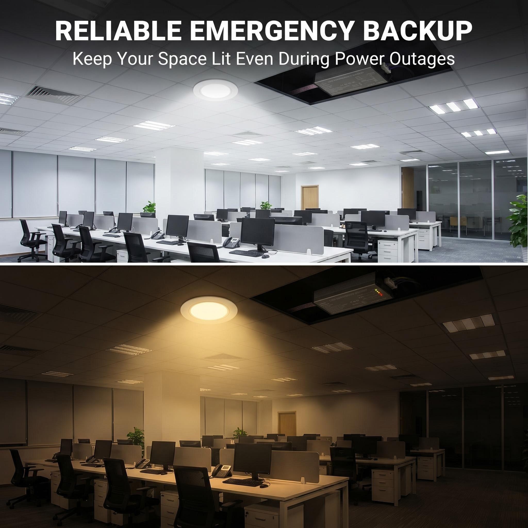
LED Emergency Driver For LED Panel Lights
Emergency drivers sized for 600×600 and 1200×300 LED panels with external drivers.
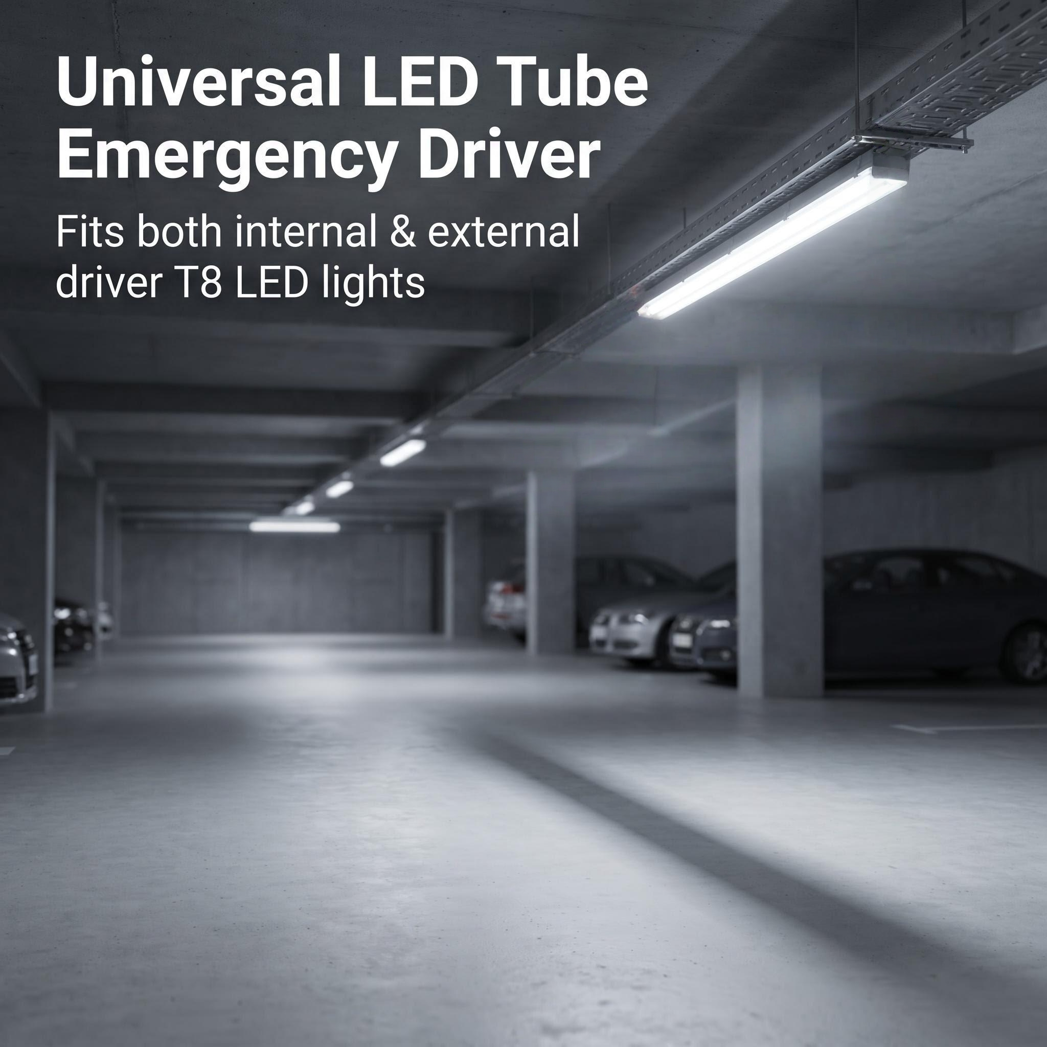
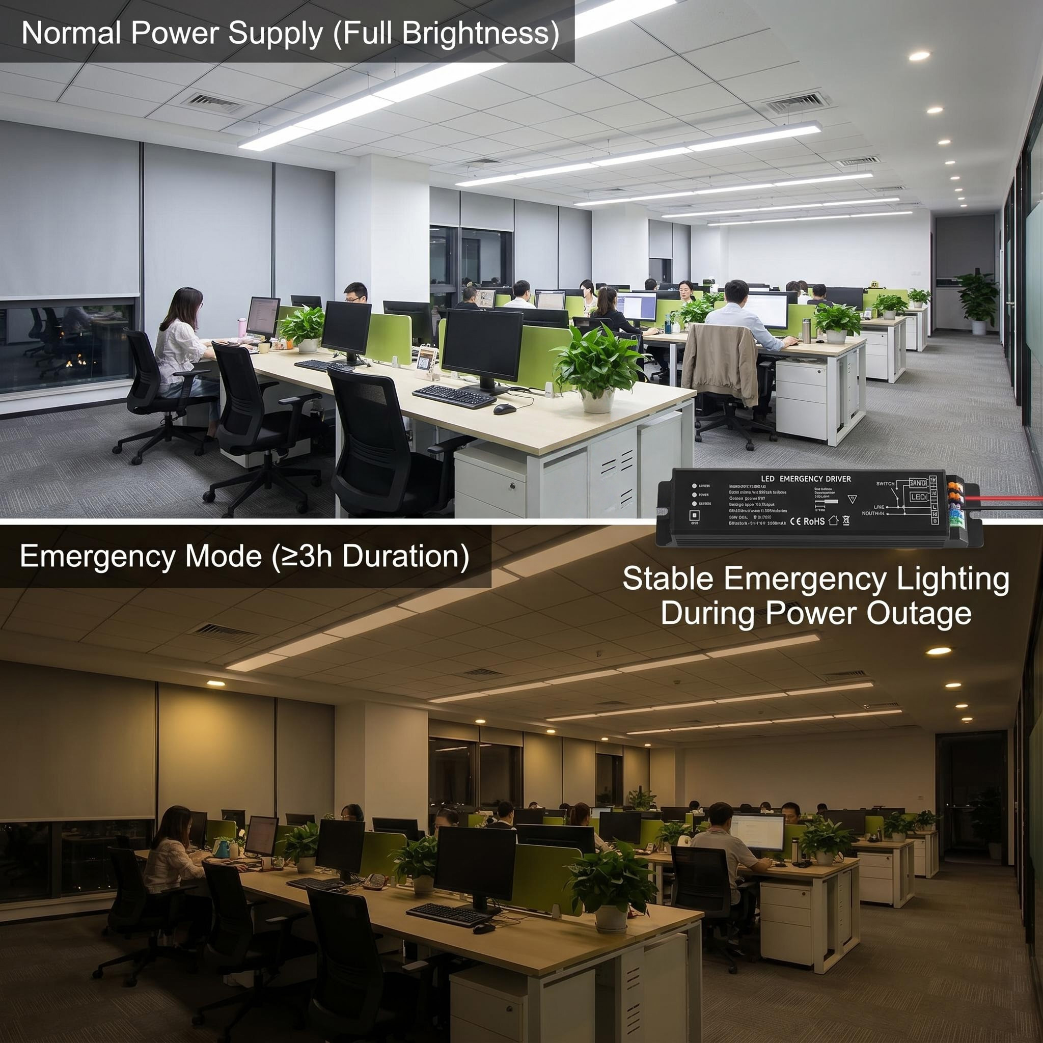
LED Emergency Driver For LED Tubes
Emergency conversion kits for T8 and T5 LED tubes and batten fittings.
LED Emergency Driver For Linear Lights
Slim emergency drivers that fit inside linear and trunking profiles without a separate battery box.
Frequently Asked Questions About LED Emergency Driver
What Makes Up The Physical Enclosure And Why It Matters
Q: What is the minimum order quantity and how does the sample policy work?
MOQ is 500 units for standard LED emergency drivers, 100 units for the LED strip line. Samples ship within 5 working days from confirmed order; sample cost is credited against the first production order. For OEM fixture trials, Hymark offers a 10-unit evaluation pack with mixed output ratings.
How To Match The Driver To Your Host Fixture
Q: How do I confirm the emergency driver suits my existing LED panel, tube, or linear fixture?
Match three parameters: normal driver output window, LED forward voltage sum, and total fixture wattage. Hymark’s LED emergency driver for LED panel lights covers DC 50-200V output at 150-350mA, handling 10-40W loads. For LED tubes and linear lights, the range is DC 30-120V at 200-500mA, 8-25W. Request the host fixture’s LED module V-I curve to verify compatibility.
Emergency Duration And Output Options
Q: What emergency duration and output levels are available?
Standard durations are 90 minutes, 2 hours, and 3 hours per EN 1838 and BS 5266-1. Output is expressed as a percentage of normal lumens: 10% for escape route minimum, 50% for open area anti-panic, or 100% full power for high-risk task areas. A 40W panel driven at 50% emergency output yields roughly 2000-2400 maintained lumens depending on LED efficacy.
Wiring Configuration And Installation
Q: What is the difference between maintained and non-maintained wiring?
Non-maintained uses a separate switched live to the emergency driver; the lamp is off during normal mains, energised only on battery. Maintained wiring requires a permanent live plus switched live, keeping the lamp energised at all times with seamless changeover via relay. Maintained circuits cost more in cable but satisfy regulations where normal illumination must never extinguish.
Testing And Compliance Features
Q: What self-test options are available and what do they cost to add?
Manual test key is standard. Automatic self-test per EN 62034 adds roughly 8-12% to unit cost; it performs brief functional tests monthly and duration tests annually, logging faults via LED status blink codes. Full DALI-2 emergency test facility adds 15-20% and enables remote monitoring, annual test reporting, and addressable fault location across large installations.
Battery Technology And Service Life
Q: What battery chemistry is used and how often must it be replaced?
Hymark uses LiFePO4 3.2V packs (1500mAh to 6000mAh depending on duration and load) or Li-ion 18650 3.6V configurations where space is constrained. NiCd 3.6V remains available for markets with strict disposal infrastructure. LiFePO4 achieves 500-800 cycles to 80% capacity; replacement interval is 4-6 years under EN 62034 self-test regimes versus 2-3 years for NiCd in the same thermal conditions.
Lead Time And Logistics
Q: What is the production lead time and how do lithium batteries affect shipping?
Standard lead time is 25-30 days after deposit. LiFePO4 and Li-ion packs require UN 38.3 test summary documents for air freight (IATA PI 965 Section IB) and IMDG Code SP 188 for sea freight; this adds 3-5 days to documentation and restricts some carrier routes. Sea freight FOB Shenzhen is standard; CIF to major ports available. Express courier for samples uses UN 38.3 certified 4G fibreboard boxes with 1.2m drop test marks.
Certification Documentation And Export Practicalities
Q: Which test reports and conformity marks can be supplied for my destination market?
Hymark can supply third-party test reports to EN 60598-2-22, EN 1838, EN 62034, IEC 61347, and UL 924. Buyers should verify which certificates the supplier holds for their specific model and request the CB test certificate or EU-type examination for CE marking. For UKCA, Saudi CB, or SASO, confirm the notified body number on the documentation matches the product label.
Commercial Terms And Support
Q: What are the payment terms, warranty, and installation support?
Payment is 30% deposit, 70% against B/L copy for orders under USD 50,000; L/C at sight available above. Warranty is 3 years on the driver, 2 years on battery packs. Spare battery packs are stocked for 5 years after model discontinuation. Installation manuals include wiring schematics for maintained and non-maintained circuits; commissioning support is available via video call for orders over 1000 units.
OEM Branding And Packaging
Q: Can the driver be supplied with private branding and custom packaging?
OEM labelling with customer logo and model code is available from 1000 units, 3-4 weeks additional for silkscreen and carton artwork. Standard export carton is 20 units per inner box, 200 units per pallet; lithium battery shipments use UN-certified 4G fibreboard with hazard labels and 1.2m drop test certification marks. Pallet dimensions are 1200x1000mm, gross weight 18-22kg per carton depending on battery capacity.
Important Notice
Specifications, output and duration figures and price ranges in this guide are indicative and are provided
for planning purposes only. Actual emergency output, duration, battery life, ingress protection and available conformity documentation
differ by model and by destination country, and emergency lighting design remains the responsibility of the project designer. Buyers
must confirm their own mains voltage and frequency, the emergency lighting standard enforced locally, the host fixture compatibility
and their import requirements before placing an order. All figures are subject to written confirmation in the final proforma invoice
issued by Hymark.
Sourcing LED Emergency Driver from Hymark
What to Request in Your Technical File
A complete data package from any emergency driver supplier should include the bill of materials for each sub-assembly: enclosure flame-retardant grade (typically UL 94 V-0), charging IC part number and CC/CV set points, battery cell manufacturer and batch test records, inverter switching frequency and efficiency curve at 25% and 100% load, changeover relay contact rating and mechanical endurance cycles, indicator LED wavelength and viewing angle, plus the test facility logic diagram for self-test or DALI protocol implementation. Ask for the thermal images at 45°C ambient after 90 minutes of emergency operation. If the supplier cannot provide these, you are buying on faith.
How Hymark Structures Its LED Emergency Driver Range
Hymark builds its LED emergency drivers for panel lights, tubes and linear lights around LiFePO4 3.2V packs from 1500mAh to 6000mAh, delivering 3W to 15W emergency output for 90 minutes, 2 hours or 3 hours. Input voltage spans AC 85-265V or 100-277V depending on the SKU. The constant current inverter output window is typically DC 12-80V at 150-500mA, covering LED loads from 3W to 25W in normal mode. Changeover is handled by a latching relay rated for 100,000 electrical cycles at 5A. Self-test and DALI test facility variants are available; manual test key remains standard. Non-maintained wiring is default, with maintained wiring available on request for compatible fixtures. Ambient temperature range is -10°C to +50°C. Charge time to 90% capacity is 16-20 hours from flat. Cycle life for LiFePO4 is 800 to 1200 full depth-of-discharge cycles versus 300 to 500 for equivalent NiCd 3.6V packs.
The Sourcing Decision
JIALINGHANG ELECTRONIC CO., LTD. was founded in 2013 as a global LED exporter in general illumination. A strategic shift in 2017 refocused the company on LED emergency technology and high performance LED strips. Hymark was launched in 2026 as the premium brand. Products are co-designed and engineered in house through a strategic partnership with dedicated manufacturing facilities that have also been operating since 2013, and the company manages R&D, product design and global distribution itself. The range covers emergency lighting, emergency exit signs, emergency luminaires, emergency twin spotlights, LED emergency drivers for LED high bays, panel lights, tubes and linear lights, full power output emergency drivers, LED strip lights, COB LED strips and SMD LED strips.
Orders are supplied with selectable emergency duration, maintained or non-maintained wiring, OEM and ODM branding, export carton packing and FOB or CIF terms.
Send your host fixture type and wattage, the emergency duration your code requires, your mains voltage and your destination port to receive a quotation within 24 hours via WhatsApp or email.
Get a Factory Direct Quote on LED Emergency Driver
JIALINGHANG ELECTRONIC CO., LTD. has been in LED lighting since 2013 and has focused on
LED emergency technology and high performance LED strips since 2017. Hymark products are co-designed with our
dedicated manufacturing partners, built with selectable emergency duration and maintained or non-maintained wiring, and function
tested before packing. Send us the host fixture type and wattage, the emergency duration your local code requires, your mains
voltage and your destination port and we will return a quotation within 24 hours.


 English
  Spanish
  Arabic
  French
  German
  Russian
  Portuguese
  Italian
  Vietnamese